Performance Factors of Basic Logic Gates
A logic gate is an electronic circuit that outputs based on predetermined values. it has more than one input and one output signal. the output depends on the combinations of the input signals.
logic gates are an important part of the digital system that changes the previous history of the digital system. The hardware logic function is based on logical decisions.
There are only two values either "0" or "1" in a logical algebra which is a unique property of the logic algebra system. Logic gates are based on different IC families. the most prominent family of logic systems are Transistor-Transistor Logic(TTL), metal oxide semiconductor(MOS), Complementary Metal oxide semiconductor(CMOS), and Emitter coupled Logic(ECL).
In this article, we discuss Different types of logic gates, their tables, diagrams etc. We also discuss the different performance factors of logic gates.
Positive Logic
positive logic is defined as two states of logic one state is "high" which is called 5 volts and another state is "low" which is called 0 volts. This type of logic system is called positive logic.
In positive logic, 1 represents as- An ON circuit
- A Closed Switch
- A High Voltage
- A Plus Sign
- A True Statement
Negative Logic
Negative logic is defined as because of two states one state is "high" which is called 0 volts and another state is "low" which is called 5 volts. This type of logic system is called Negative logic.
In negative Logic, 0 represents as- An OFF circuit
- An Open Switch
- A Low Voltage
- A Minus Sign
- A False Statement
But is not necessary that 1 represents a 5 voltage in a positive system and 0 represents a 0 voltage in a negative system. For example, for any circuit, if I say two-state of 5 volts and 9 volts which shows the low voltage of 5 volts and high voltage is 9 volts in the positive logic system and in the negative system the vice versa system is implemented.
Types Of Logic Gates
Many types of logic gates are used in digital systems. but in this article, we discuss 3 basic logic gates and also discuss the performance factor of different logic gates defined below with the help of a table, symbol etc.
- And Gate
- OR Gate
- Not Gate
And Gate
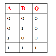
The 2 inputs And gate have a total number of input combinations is 4. If we take 3 inputs of the logic gate the combinations of input are 8. there are two ways to define the gate one is by their symbol system and the other is equivalent to a switching circuit. both circuit symbol is shown below.
Symbol of And gate
2 input AND gate table
 |
| 2 Inpur And Gate Table |
3 Input AND Gate Table
 | |
|
Operation of And Gate
- The AND gate has output "1" when Both inputs of the And gate are high in a two-input logic gate.
- The AND gate has output "0" when Both inputs of the And gate are Low in a two-input logic gate.
- If one input is high and the other input is low the output of the AND gate is also low.
- If one input is "A" low and the other input "B" is high the output of the AND gate is also low.
Boolean Expression
OR Gate
The 2 input OR gates have a total number of input combinations is 4 of each input. if we take 3 inputs of the logic gate the combinations of inputs are 8. Both the logic symbol and circuit symbol are shown below.
Symbol of OR Gate
The OR gate has output "1" when one of the inputs of or gate is high in a two-input logic gate. The OR gate has output "0" when Both inputs of the OR gate are Low in a two-input logic gate.
If one input is high and the other input is low the output of the OR gate is also High. If one input is "A" low and the other input "B" is high the output of the OR gate is also high.
Not Gate
Not gate is the complementary gate that inverts the input signal compared to the output signal. the other name for NOT gate is called an inverter.
Symbol of Not Gate

Truth Table of Not Gate
Operation of Not Gate
The working of not gate is simple when the input is high the output of the inverter is low and when the input is low the output of the gate is high.
Boolean ExpressionLogic Gate Performance Factors
- Supply Voltage
- Input Voltage
- Input And Output Currents
- Output Voltage
- Fan-in
- Fan out
- Propagation Delay Time
- Noise Immunity
- Power
Supply Voltage
Input Voltage
Output Voltage
Input & Output Currents
The input current level of any gate depends on the input voltage. the gate output current is also dependent on the output voltage.
Fan-in
The number of inputs in a logic gate is defined as fan-in.
Fan out
The ratio of Iol(max) and Iil(min) is called fanout.
Propagation Delay Time
The switching speed of the logic gate is defined as propagation delay time. the time when a logic gate changes there condition from low output to high output. the time depends on the load and maybe a transistor in saturation condition.
Noise Immunity
There are two types of noise margin
- low state noise margin
- high state noise margin
Low State Noise Margin
Noise Immunity is defined as the difference between Vol(max) and Vil(max) and is called low state noise margin.
High State Noise Margin
Power
when switching in any circuit the power is dissipated across the resistance. The high switching means high power dissipation in the logic gate.


.png)


0 Comments
please do not insert spam links