Method Of Neutral Grounding
Earthing, also known as grounding, is an important electrical safety practice connecting electrical systems and devices to the Earth. The primary purpose of earthing is to ensure the safety of people and equipment by providing a low-resistance path for fault currents to flow into the ground, preventing the buildup of excessive voltage.
Earth Value Resistance Range
- Low Resistance: value below 5 ohms
- Moderate Resistance: 5 to 25 ohms
- High Resistance: Values above 25 ohm
Importance of Earthing
- Earthing provides the safety to prevent the buildup of dangerous voltages in electrical systems, reducing the risk of electric shock and fire hazards.
- It provides an easy path for fault currents to safely dissipate into the ground.
- It minimizes electromagnetic interference and improves the overall performance of electronic systems.
- we remove the possibility of the arching ground by using grounding/earthing.
- we use earth faults to operate the protective relays.
- The operating and maintenance costs are low.
- The system becomes stable and reliable.
- The protection of the system is increased by using earthing.
- we protect the system from overcurrent using grounding.
- This system provides protection against the lightning effect.
- To earth, the system's overall efficiency is increased.
- we gain a stable neutral point.
- The circuit breaker protects the unnecessary tripping.
- Using fuses and relays at the earth's fault we save human life and equipment life.
- The lifetime of machines is increased by using a grounding system.
Types Of Grounding
- Resistance Earthing
- Reactance Earthing
- Solid Earthing
- Peterson coil Grounding
Resistance Earthing
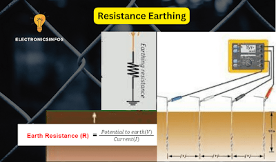
Resistance earthing is a safety feature of an electrical system. It involves connecting the system to the ground. The purpose of resistance earth is to control the faulty electric current and protect the system from potential damage.
 |
| Resistance Earthing |
Imagine it as putting speed bumps on a road. These "resistances" slow down and limit the flow of electricity, acting as a safeguard. Doing this ensures that faulty currents, stress, and shocks don't harm our electrical equipment. It's like adding a shield to keep everything safe.
Resistance earthing also helps reduce sudden voltage drops, making the whole system more stable.
Mathematically, the relation between the earth's resistance and current is shown below
According to the Ohm Law
According to the Law of Resistance
- In this method, we use series resistance between Neutral and Earth.
- In resistance grounding the fault current value is low.
- The range of systems where we used"resistance Earthing " is between 3.3kv to 22kv.
- This is a reliable method to protect the system.
- Radio interference is low in communication lines.
- The arching ground is low in this system.
- we used a specific type of protective gear system in resistance grounding.
- The transient voltage is low.
- Switching is not affected by the resistance value.
- The chance of breaker burnout is low.
- The arc is not dead by itself.
- The mechanical stress is low.
- In This Method, we reduced the fault current by 5 - 20 %.
Reactance Earthing
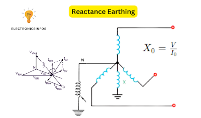
Reactance earthing is a method used in electrical systems to limit the flow of fault currents and to improve safety. Reactance earthing is a type of earthing in which we put a reactor between the neutral and the earth. The important element in reactance is reduced faulty current. Reactance earthing system is expensive as compared to solid earthing but less expensive than resistance earthing.
 |
| Reactance Earthing |
The reactance earthing resistance, often denoted as (X), can be calculated using the following formula
X0 = V/I
Where
- (X0) is the reactance earthing resistance,
- (V) is the voltage of the power system during a fault condition, and
- (I0) is the fault current.
Advantages of Reactance Earthing
- In this method, we connect the reactor between neutral and earth to protect the system.
- Reactance is stable so the fault current is low.
- The Voltage Range of Reactance Earthing is between 11kv to 22kv.
- Reactance Earthing is a reliable method.
- The cost of the Reactance Earthing system is medium.
- The arching ground is low in the Reactance Earthing.
- In this method, we used specific protective gear to secure the system.
- The possibility of breaker contact is burnout is available.
- The arc does not minimize himself so we need to minimize by another method.
- Mechanical stress value is medium in reactance Earth system.
- The shocking possibility is available
- Reactance earthing limits the earth's fault by the current 25 %.
Solid Earthing
Solid Earthing is a type of earthing in which a generator, transformer or earthing transformer is directly connected to earth stations is called solid earthing. it is necessary for a solid earth system if the three-phase fault current is 25 % to 100% as compared to an earth fault current to stop the high transient voltage.
It's a straightforward method where the system is securely linked to the earth using materials like copper or aluminium. This connection helps ensure safety and provides a reliable path for any excess electrical currents to flow into the ground, preventing damage to the system.
 |
| Solid Earthing |
Advantages of Solid Earthing
- In this method, we directly connect neutral to the Earth station.
- Fault current is low in the Solid Earth Method.
- A solid earthing method is used in the below 660v circuits.
- The interference is minimal in communication lines.
- System cost is low because we do not need extra types of equipment.
- The arching ground is low in the solid earthing.
- A solid Earthing system needs specific protective gear to protect the system.
- Transient voltage is low in solid Earth systems.
- Switching has not affected the system Directly.
Peterson coil Grounding
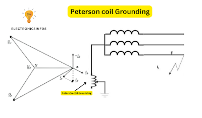
A Peterson coil is a type of grounding device used in electrical power systems to improve the system efficiency of ground fault protection. It is employed in high-voltage systems, such as electrical substations etc.
The coil is named after its inventor, Charles F. Peterson. It works by creating a specific magnetic field, and when there's a ground fault (an abnormal flow of electricity to the ground), this coil reacts and helps the system figure out where the problem is.
 |
| Peterson Coil Earthing Method |
we find the coil resonance with the below formula
L = 1/3ѠC
To neutralize the exact value of line capacitive current we Regulate the value of L between 90-110%.in fault conditions, The coil reduces the arc current so the system becomes stable.
Advantages of Peterson Coil Grounding
- In this method, we use a variable reactor between neutral and earth.
- Peterson coil completely zeros the fault current.
- Peterson coils are used for up to 66kv.
- Peterson coils are the most reliable system.
- External interference in the communication lines is minimal in this system.
- The Peterson coil system is expensive.
- we completely remove the arching ground.
- Specific protective gear is used in the Peterson Coils System.
- The value of transient voltage is high.
- During switching the trend of reactance is high.
- The breaker contact is secure in this system.
- There is no mechanical stress.
Applications Of Earthing
- Earthing is essential in homes to safeguard residents from electric shock and protect appliances.
- Industries use earthing to ensure the safety of workers and protect machinery and equipment.
- In power distribution systems, earthing is critical to prevent overvoltages and ensure the proper functioning of transformers and other electrical components.
- Earthing is a fundamental part of electrical safety with different applications to protect people, and equipment, and ensure the proper functioning of electrical systems.


.png)


0 Comments
please do not insert spam links