EMF Equation of Electrical Transformer
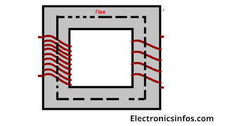
The Emf Equation of an electrical transformer is a Mathematical Expression that defines the relationship of Primary Induced voltages to Secondary Induced voltages. when we connect the transformer through the alternating supply to the primary side the alternating current is produced on the primary side. This primary current is called induced current which is also alternating in nature. This alternating current produced a flux that is also alternating in nature. The flux passes through the magnetic core which provides a low reluctance path. This primary flux links with the secondary side of the transformer and according to the Faraday law of electromagnetic induction the emf is produced in the secondary side that is directly proportional to the change of primary link flux. The mathematical equation defines that the change of flux for the time defines the induced emf.
Transformation Ratio of the Transformer
In electrical engineering, the transformation ratio of a transformer is the ratio of the number of turns in the primary winding to the number of turns in the secondary winding. This ratio determines how voltage is transformed from the primary side to the secondary side. The transformation ratio (K) is calculated using the formula
where is the number of turns in the primary winding, and is the number of turns in the secondary winding.
Step-up Transformer
IF
N2 > N1,
K>1
The transformer steps up in nature in voltage.
So let's do a mathematical expression which defines the EMF equation of the Electrical transformer
let us say
Np= No of tunes on primary
Ns= No of turns on secondary
Øm = Maximum value of Flux
f = Frequency (c/s)
The flux increases from zero to Øm in 1/4 cycle
∵ The average rate of change of flux = 4Ømf (WB/sec)
∵ The average EMF induced in each term is = 4*Øm*f (volts)
Assuming the flux Ø to vary sinusoidally, then a sinusoidal emf
will be induced in each turn of both windings.
For a sine wave, form factor = Rms/Mean= 1.11
∵ RMS emf induced in each turn
1.11*4*Øm*f (volts)
∵ RMS emf induced in primary
Ep= 4.44*Øm*f*Np (volts)
∵ RMS emf induced in Secondary
Es= 4.44*Øm*f*Ns (volts)
Alternative Method Of Finding EMF
EMF = No of turns* Change of flux per unit time
EMF = - N dØ/dt
N= number of turns
dØ= instantaneous flux
dt = change of time
minus = minus represents the Lenz law
Let The Flux Wave Represent by
Ø=Ømsin wt
The emf induced in the primary is
Eind= -N dØ/dt volts
= -Np*w*Øm*cos wt volts
=Np*w*sin(wt-90°) volts
The max value of induced EMF =
Np*2*π*f*Øm
RMS value of Induced EMF =
4.44*f*Øm*Np volts ∵ in primary
4.44*f*Øm*Ns volts ∵ in secondary
Relationship between Voltage and Current
The relationship between voltage and current is indirect. if the primary voltage is high the primary current is low and vice versa.
E1/E2 = I2/I1
Relationship between Voltage and turns
The relationship of primary voltage E1 is a direct relation to primary turns N1
E1/E2 = N1/N2
Related
Posts :
How to Reduce The Transformer Losses?
Single Phase Transformer Vs Three Phase
Transformer
3 Types of Electrical Transformers w.r.t
Core
Regulations of Electrical Transformer?


.png)

.png)


0 Comments
please do not insert spam links