What is Electrical Earthing?
Electrical earthing, also known as grounding, is a fundamental safety mechanism used in electrical systems to prevent electric shock and damage to appliances.
It involves connecting the non-insulating parts of an electrical system, such as the metal casing of an appliance, to the earth.
We know that the ideal path for current flowing is low resistance, For this purpose, we provide a low resistance path for the current.
Earthing can be implemented in various ways, including using a metal rod driven into the ground or a conductive plate buried below the surface and a PME system.
Importance Of Earthing
Advantages of Earthing system
- Earthing provides safety for human life and equipment.
- It also protects the system from becoming unstable.
- It protects the short circuit
- This helps minimize the risk of fire.
- Earthing is essential in dissipating static electricity in industries.
- It helps stabilize voltage levels.
- Proper grounding helps reduce electromagnetic interference (EMI) and radiofrequency interference (RFI).
- Earthing prevents damage to structures and equipment against lightning.
- Grounding establishes a stable reference potential for electrical systems.
- It provides protection against overvoltage and short-circuit current.
- Easily found the line-to-ground fault
Types of Earthing
There are two types of earthing including
- Equipment earthing
- System Earthing
Equipment Earthing
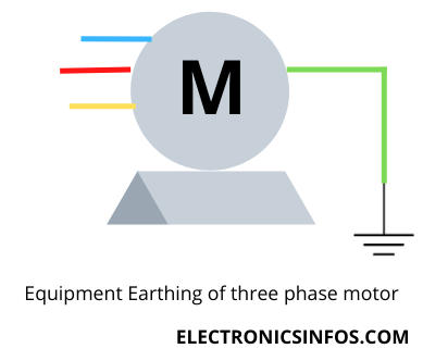
Equipment earthing is a part of earthing in which we connect our equipment (Generators, Motors, Transformers etc) to the earth is called Equipment Earthing.
Equipment earthing, also known as grounding, is a crucial part of electrical systems that connects the electrical equipment's non-current-carrying parts to the earth. The primary purpose of equipment earthing is to ensure safety, protect against faults, and provide a stable reference potential for the proper functioning of electrical devices. There are three methods of equipment earthing, including
- Direct Earthing
- Equipment Grounding Conductor (EGC)
- Grounding Electrode System
System Earthing
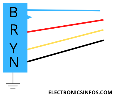
System Earthing is a part of Earthing in which we connect a machine's neutral wire to the Earth called System Earthing. In power distribution systems, the neutral point of transformers is often grounded. This neutral earthing helps balance the system voltages and provides a reference point for phase voltages.
Types of System Earthing
There are several methods of system earthing, including
- Solid Grounding
- Resistance Grounding
- Reactance Grounding
- Direct Earthing
- By Earth plate or Equipment Grounding Conductor (EGC)
- By Copper Rod Electrode or Grounding Electrode System
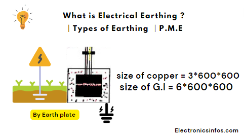
By Earth plate
when we earthing by the earth's plate first we need to test the soil. we select those which provide low resistance after testing the soil we buried a copper plate or G.I. galvanised Iron Plate at a depth of 20 ft to 25 ft.
 |
| Earthing by Earth plate |
The area of soil is 5*5 ft. We use 8 SWG copper wire to connect the earth plate with the corner hole.
after that, we put out the earth continuity conductor with the help of a conduit pipe and connected this earth continuity conductor to the machine's metallic part. we buried an earth plate 5ft forward of the base point.
Size of earth plate
- size of copper = 3*600*600 (T*L*W)
- size of G.I = 6*600*600(T*L*W)
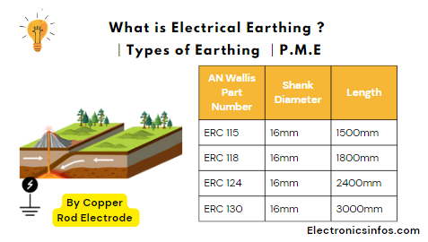
By Copper Rod Electrode
we use this method in different countries. The copper rod electrode earthing method is frequently used where water is easily found. this method is used where we easily found wet mud In this method we used a 12ft copper electrode which consists of three parts each path length is 4 ft. The diameter of this rod is 12.5mm to 25mm. all these parts connect with screws. the upper part of the copper electrode is steel coated and the remaining part is copper.
 |
| Earthing by earth rod |
Components Of Earthing
- Earth Continuity Conductor
- Earthing Lead
- Earth Electrode
Earth Continuity Conductor
An earth continuity conductor is a conductor which connects the metallic part of the machine to the earthing lead is called the earth continuity conductor. we use copper wire as an earth wire. The earth wire's size depends upon the load current's maximum size.
Earthing Lead
those wires which are connected to the earth's continuity conductor and earth electrode are called earthing lead and these two points are called connecting points. the earthing lead is also made with copper. to protect the earthing lead we use a G.I pipe. we connect at least two points of the earth's plate.Earth Electrode
- size of copper = 1/8*2'*2' (T*L*W)
- size of G.I = 1/4*2'*2'(T*L*W)
Double Earthing
Double earthing is a critical safety measure in electrical systems, particularly for three-phase machines. It involves creating two separate connections to the ground, providing a different electrical current path.
 |
| Double Earthing |
The primary purpose of double earthing is to protect both the equipment and the individuals working on or near it from electric shock, fire hazards, and other potential dangers.
By lowering the overall resistance to the ground, double earthing enhances the effectiveness of the protective measures and ensures a more reliable and safer electrical system.
Benefits of Double Earthing
- Double earthing Offers a backup path for electrical current that reduces the risk of electric shock.
- It prevents power outages and equipment failures by providing redundancy in grounding paths.
- It stabilises voltage levels and reduces electrical noise.
- It ensures efficient fault clearance, which minimizes stress on electrical components.
- It meets safety regulations, which often mandate double earthing for electrical installations.
Protective Multiple Earthing (P.M.E )
Difference between Earth and Ground
Earthing
- Earthing protects from electric shocks
- the standard wire colour is green
- is located under the earth to protect the system
Grounding
- Grounding is used to protect the whole system.
- the standard colour of the ground wire is black
Applications of Earthing
- In Electrical Systems Earthin provides Safety, Equipment Protection
- and Stability.
- Earthing used in Buildings, Structures and Electronic Systems against Lightning.
- In the Telecommunications Sector earthing is used to improve the Signal Quality and secure the Equipment.
- In Industry, earthing is used for Worker Safety and Equipment Protection.
- In Medical earthing is used for Patient Safety and proper Equipment Functionality.
- In Oil and Gas Industry earthing provide safety against Explosion.
Conclusions
The conclusion of various methods of earthing is that each method serves the fundamental purpose of protecting people and property from electrical hazards.
Plate earthing, rod earthing, and pipe earthing are common methods, each chosen based on specific criteria such as soil resistivity and electrical load requirements.
The selection of an earthing method is crucial and should be made considering the environmental conditions, the type of installation, and the safety regulations applicable to the area.
Frequently Asked Questions – FAQs
What is an electrical earthing system?
What are the types of electrical earthing systems?
Why is electrical earthing important?
How is an electrical earthing system installed?
What are the components of an electrical earthing system?
How do you test the effectiveness of an earthing system?
What are the common problems with electrical earthing systems?
- high earth resistance due to poor soil conductivity,
- inadequate electrode placement,
- corrosion of connections,
- lack of maintenance.
What are the regulations and standards for electrical earthing?
Can an electrical earthing system be upgraded or modified?
How does electrical earthing differ in industrial and residential settings?
Related Posts


.png)


0 Comments
please do not insert spam links